What do you do exactly when you’ve already replaced the camshaft sensor but error codes still show up? The replacement should’ve solved all problems, but here you have your vehicle telling you there are new ones. How do you move forward? Can it still be fixed?
An error code still appears even after replacing the camshaft sensor because the power supply, ground circuit, or signal circuit wires have malfunctioned. Additionally, the replacement sensor may have damages. To fix, test the wires or get a new sensor.
This article will discuss the mechanisms that allow specific error codes to appear and give detailed instructions on how to fix them! Let me help you get rid of those pesky errors! Let’s start!
What Causes Error Code After Replacing the Camshaft Sensor
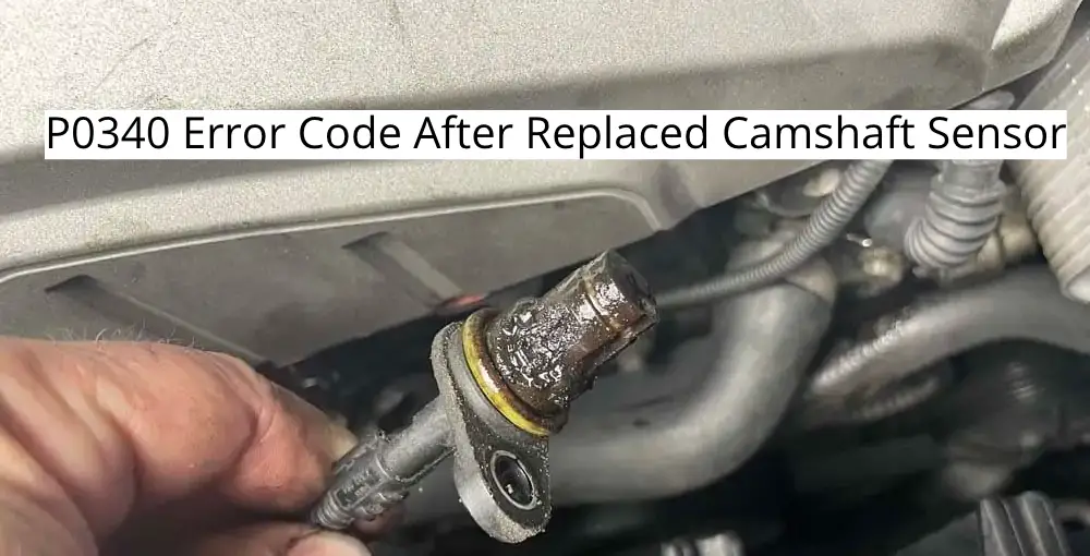
The error you’re referring to is most likely the P0340 error. When you get this error, don’t automatically assume that the camshaft sensor is bad.
A possible culprit could be the wiring going to and from the sensor, which has become faulty due to wear and tear.
Note that when your engine is getting the code, this means that the report it is getting from the sensor isn’t readable. Assuming that the wiring has gone bad due to wear and tear, it’s highly possible that the engine isn’t getting any reading at all.
Another possibility are reports that do not make sense. Examples of these are sensor reports that may not be appropriate to the actual driving conditions. For example, you are driving on desert terrain, and the camshaft position produces a report.
If the engine control module (ECM) deems the report does not reflect how the engine components should be oriented on desert terrain, it produces the error.
Note that other sensors are working throughout your engine, and the ECM anticipates that the reports are coherent.
If all other sensors say one thing and the camshaft sensor by itself says another, it interprets the sensor as the faulty component.
How the Camshaft Position Sensor Works
Part of understanding the value of the sensor is learning how the camshaft operates. As the name suggests, the camshaft contains a series of cams that move precisely to achieve specific motions.
In your vehicle, the exact position of the camshaft determines the stroke of the cylinders, the proper time to ignite, and the appropriate time to inject fuel. The CPS is necessary because it relays the information it gathers to the rest of the engine.
The function of the camshaft position sensor is actually similar to the Injector Control Pressure sensor which I have already written about. Yes yes, sensors tend to be fragile components.
The reports it produces are sent to the engine control module (ECM) which you can think of as the brain of the engine. With the report it gathers from the CPS, the ECM gives out commands on the proper positioning of the camshaft to achieve maximum efficiency.
This allows your vehicle to save on fuel, attain the proper horsepower, and be more environmentally friendly by minimizing emissions.
Between the camshaft and CPS is a gap that transmits the motions of the camshaft to the CPS receivers. The motions are translated as sine waves, and the CPS transmits the report via the signal return wire. The CPS gets the reports from the ECM, and the cycle continues.
Testing the Camshaft Position Sensor
As you may know by now, the CPS is integrated into the engine via a complex wire system. As such, there are many possible culprits for the error code.
You should conduct several tests to know what exactly needs to be done.
The tests to be conducted are:
- Wiring Check
- CPS Power Supply Test
- CPS Ground Circuit Test
- CPS Signal Circuit Test
- Camshaft Sensor Positioning Test
1. Finding The Camshaft Position Sensor (CPS)
If you’ve replaced the sensor on your own, you can probably skip this part. But if you’ve had the replacement done by a mechanic and don’t want to go on another trip to the repair shop, read this.
To find the CPS, ensure your car is parked on even ground. When working with sensors, it’s essential to disconnect the negative battery cable.
In many models, the filter housing prevents access to the sensor, so remove the housing first. Many mechanics tend to work on the CPS from under the vehicle, but it’s possible to access it from the top. It all depends on your vehicle’s makeup.
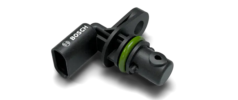
Most CPS are shaped like an upside-down L. The base is tubular, and the top is horizontally attached to the rest of the engine via wires.
Detach the sensor from the wires and take the time to see if oil has gotten in. Remove the bolt that holds the sensor in place. A 10-millimeter (0.39 in) would do the trick.
2. Wiring Check
Now that the CPS is out, you can check on the wires. Many camshaft sensors have three major wires connected to them. The first wire provides the sensor its power. For some models, this is colored orange.
Another wire grounds the electricity that passes through the component. Basically, the excess voltage is managed by this wire which is often colored brown.
The third wire plays the crucial role of transmitting the signals to and from the ECM. Correctly understanding the wires and their roles is crucial before moving on to the next steps.
It is also important for you to refer to your vehicle manual as the appearance of the wiring and components may be vastly different.
3. CPS Power Supply Test
Here’s how you can do a power supply test properly:
- Turn on the ignition. What you will do is check the voltage that passes through the wires and the pins. This can be done by using a multimeter. 2.
- Test the voltage on the pin connected to the power supply wire.
- Stick one of the multimeter prongs on the pin and check the multimeter’s reading. A lot of pins have numbers on the backside. The power supply pin is labeled with the number 1 on some models.
- This should test about 5 volts. If that doesn’t work, you will have to check the power supply line that connects the sensor to the ECM. If it reads 5 volts, then the power supply line wire isn’t the issue. You may proceed to the ground circuit test. You may have to replace the power supply wire if it doesn’t.
4. CPS Ground Circuit Test
For the ground circuit test, you will check for the continuity between the wire harnesses. A circuit only has continuity if the electrical flow is complete.
Here’s how you can do a ground circuit test properly:
- Attach the prongs to the sensor and the ECM wiring harness using a multimeter. In your manual, you should see the correct connector code and the corresponding terminal number for both the CPS and the ECM.
- Refer to the vehicle manual for this. Let’s say hypothetically that your CPS has a terminal range between 1-3 and the ECM sensor has a terminal range between 33-80. Let’s also assume that the connector has an F21 code for the connector, and the ECM sensor has an F11 code. If the terminal reads 2 for the F21 CMS and the F11 ECM reads 63, then the continuity exists as it still falls within the terminal range as stated in the vehicle’s wiring diagram.
- You may proceed to the next test if the ground circuit doesn’t have problems. If there are, replace the ground circuit wire.
5. CPS Signal Circuit Test
Here’s how you can do a signal circuit test properly:
- The signal circuit test follows nearly the same steps as the ground circuit test. You will also be testing for continuity. This time, however, you will be testing the continuity between the cam sensor and the ECM harness connector.
- If you see no problems, you can also test the short-to-ground on the signal circuit. This is pretty common, so it’s better to be sure. If the wiring has no problems, then that probably means the problem is with the CPS itself. If there are, replace the signal circuit wire.
6. Examining Camshaft Positioning Sensor
Here’s how you can examine your CPS properly:
- The first thing you need to do is check how the sensor looks. Are there cracks and leaks? It may have been improperly installed.
- Once sorted out, you can test the sensor using a multimeter. This can be done by checking the resistance between two pins. In some car models, the resistance value is acceptable as long as it’s neither zero nor infinity. You are essentially looking for short circuits within the sensor through the multimeter.
- If you see a zero or infinity value, then that means the sensor has to be replaced. However, note that the accepted values for resistance differ for every car model, so always refer to the car manual.
Conclusion
A P0340 error code may not be about the sensor itself but the wires it connects to. This component tends to be fragile, so you may still have some problems even after replacement.
But, by understanding how the sensor works, you can quickly come to a workable and long-lasting solution. With just a little effort and patience, you can say goodbye to your car woes!